Note: This is documentation for version 4.11 of Source. For a different version of Source, select the relevant space by using the Spaces menu in the toolbar above
Maps
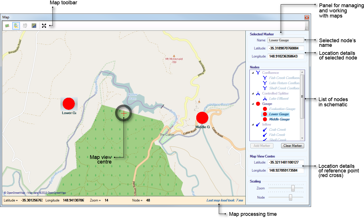
For schematic scenarios, Source provides a background map image with overlaid nodes, resulting in an enhanced view of the current active scenario.
The Map tab (Figure 1) shows nodes in a geographical setting, which can be set up using View » Maps or via the Scenario toolbar. The panel on the right allows you to manage nodes and map views. It contains the following:
- A list of nodes in the current schematic scenario;
- Tools to add and work with nodes in the map;
- Location details of a reference point (map datum), represented as a red cross; and
- A scaling feature.
Figure 1. Maps
Working with maps
Adding nodes to maps
Once your schematic is set up, you can add nodes to the map as follows:
- In the Map tab, choose the node you wish to add to the map (at this point, the node will appear greyed out or disabled); and
- Click Add Marker.
If location has not been specified, the node is positioned at the map datum by default. You can drag the node to the desired location or enter the location detail above the node list.
If location has been specified (using the Location control dialog), the node will be positioned at this location.
Once a node is added to the map, it appears enabled in the node list.
Removing nodes from a map
- Choose the node you wish to remove from the map; and
- Click Clear Marker.
Scaling
There are two types of scaling available (as shown in Figure 1):
- Zoom - expands or constricts the total geographic space rendered. This is synonymous to using the mouse scroll wheel; and
- Node - changes the rendered size of the node, so it can be adjusted for readability, independent of the current zoom. This is useful when there are several nodes in a small geographical area.
Additional features
- Hovering on top of a node will bring up a tooltip containing location details;
- To pan, right click and drag across the map;
- The panel below the map provides details at the location of the mouse pointer; and
- An approximate processing times for loading the map is also shown below the map. This value is affected by the level of zoom on the map. As the zoom level is changed, a green bar appears at the bottom, indicating that the map is in the process of being loaded.
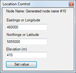
Location control
You can set geolocation coordinates and elevations for nodes and reaches using the Location Control window (using View » Location Control). While it is not essential, it is convenient to set elevations with respect to Australian Height Datum (AHD). You can enter negative numbers for components that are below sea level, such as the lower lakes of the Murray. The elevation of a component is the zero point for that component. For example, the zero point for a storage is the lowest point in the storage.
Figure 2. Location control