The Geographic Editor shows a geographic representation of the catchment model, and displays the sub-catchment map and the node-link network of the current scenario.
Figure 1. Geographic Editor contextual menu
Several commands are available when you right-click in the Geographic Editor (Figure 1):
...
- Print opens the Print preview dialog allowing you to save the geographic in the Geographic Editor as a pdf. The entire geographic is scaled to fit within a single A4 page in portrait mode.
- Save as Image saves the entire geographic in the Geographic Editor as a *.jpg. The entire geographic is scaled to fit within a single A4 page in portrait mode.
- Track when enabled, the Geographic Editor window will scroll to bring into view any node or link that you select in the Project Hierarchy. You can use this feature to locate components in large models. The default state of this button is off. In this mode, Source leaves the Geographic Editor window unchanged, regardless of any selections you may make in the Project Hierarchy.
- Note/Error icons toggles the view of any notes and/or errors that are present in the Geographic Editor.
- You can view the zoom and undertake various zoom actions using the zoom icons on the right side of the toolbar:
- Current zoom displays the value of the zoom that is currently used in the Geographic Editor. This value has a range of of 10 – 200%;
- Zoom in allows you to zoom into a particular part of the mode (or Ctrl and + on your keyboard's number pad or Ctrl and scroll up with your mouse scroll wheel). Similarly, Zoom out allows you to zoom out (or Ctrl and - on your keyboard's number pad or Ctrl and scroll down with your mouse scroll wheel). Both actions are performed in increments of approximately 10%; and
- Fit to window will display the entire model in the window.
- Show/Hide Node/Link Display - controls the view of nodes and links:
- Show link labels - when selected, show link labels
- Show node labels - when selected, show node labels
- Custom display - when selected, show customized display of nodes and link labels
- Configure custom display - by clicking this, a custom display configuration window will pop out,as shown in Figure 3. Ticking the little box to allow show Icon or show label for nodes and links
Figure 2. Geographic Editor toolbar

Figure 3. Custom Display Configuration

You can edit most Source networks within the Schematic Editor, but it is also possible to add and remove nodes and links from the Geographic Editor using the contextual menu, as follows:
- To add a new node, right-click on the Geographic Editor and enable Add Nodes in the contextual menu. Then click on the Geographic Editor at the desired location of the new node (top right schematic in Figure 4). By default, all nodes are created as confluence nodes. Subsequent clicks in the Geographic Editor will place additional new nodes. Note that Add Nodes stays enabled until it is explicitly disabled by enabling a different mode (eg. Pan or Select) from the contextual menu .
To change the node type, enable Select from the contextual menu. Click on the node of interest, which will highlight it. Right-click and choose Change Node Model. This will open another menu, which lists the node types you can change to. Select the desired node type (bottom left schematic in Figure 4). With Select enabled, you can also edit nodes and links through their respective feature editors.Anchor ChangeNodeModel ChangeNodeModel - Links can be added by enabling Add Link from the contextual menu. First, click on the upstream node (highlighted with an enlarged icon), then click on the downstream node; this will create a link. Refer to the bottom right schematic in Figure 4. Since Add Link remains enabled, subsequent pairs of clicks continue to add additional links until it is disabled. By default, a new link is configured with straight through routing. The routing type can be changed by right-clicking on the link and choosing Change Link Routing.
- Nodes and links can be deleted after Select has been enabled from the contextual menu. Click on the node or link you wish to delete (this will highlight it) and press the delete key or right-click and select Delete from the contextual menu.
Spatial coordinates and elevations for nodes and reaches can be set using Location Control.
| Note |
|---|
| When deleting nodes and links, there is no warning given, and no confirmation is sought. When a node is deleted, all links immediately upstream or downstream of the node are deleted as well. This action cannot be undone |
Figure 4. Geographic editor (Network editing)
| Info | ||
|---|---|---|
| ||
| Note: Sub-catchment runoff is fed into links, so deleting the receiving link, that is, the link associated with the sub-catchment, effectively stops that catchment runoff from entering the system. When this happens, the sub-catchment boundary is highlighted in red to indicate that it is disconnected from the network. |
To reconnect a disconnected sub-catchment to the network:
...
Figure 6. Node, link and sub-catchment deactivation in a catchment scenario
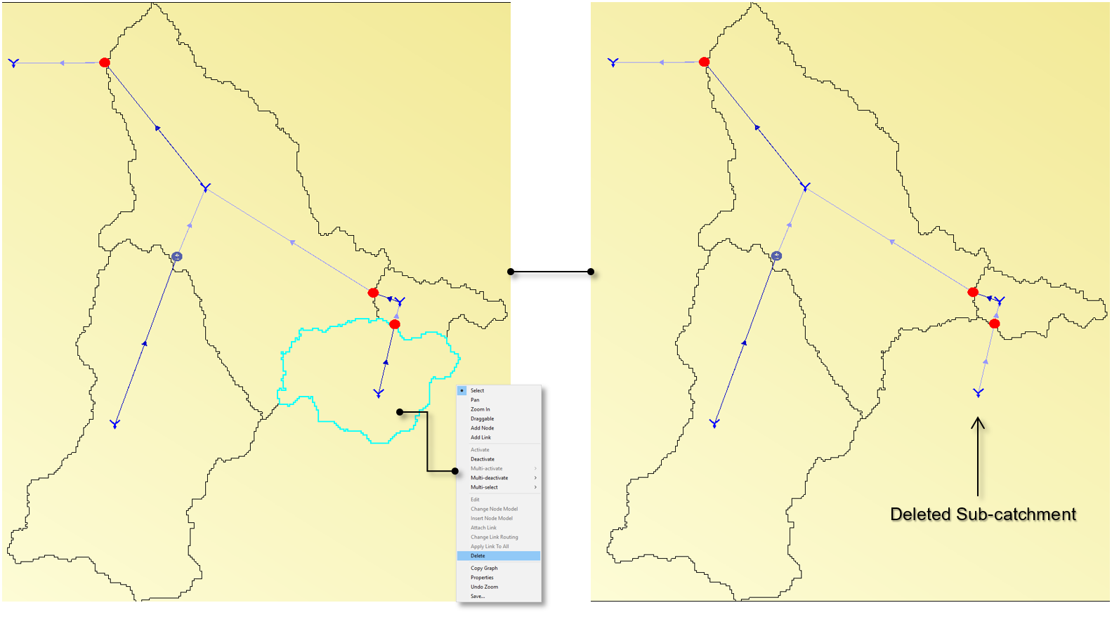
Deleting Sub-catchments
Individual Sub-catchments can be selected and deleted from the project (Figure 7). To delete a Sub-catchment, select the sub-catchment and then right click to bring up the menu. Select delete and the selected sub-catchment will be deleted. Multiple items can be selected in the one operation, and if 10 or more items are selected a warning will be displayed before the deletion is completed. Care needs to be taken when doing this because once an item is deleted all underlying configuration for that item is lost from the model.
Figure 7. Deleting a Sub-catchment