Rainwater tanks allow for the simulation of a range of stormwater harvesting and re-use strategies, which may have benefits both for potable water conservation, and also for restoration of flow regimes towards the pre-development level.
Rainwater Tank Properties
The rainwater tank properties dialogue box contains the parameters that describe the basic physical characteristics of the rainwater tank. A description of each of the parameters is given below.
A conceptual diagram of the rainwater tank properties in music is presented below:
Conceptual diagram of rainwater tank properties.
Location
The location name will be displayed under the rainwater tank node icon on the main worksheet.
Inlet Properties
The Inlet Properties define the physical characteristics of the inlet section of the rainwater tank.
Flow is hydrologically routed through the rainwater tank, based on the characteristics defined by the user.
Low Flow Bypass
All of the stormwater that approaches the pond below the user-defined Low Flow Bypass amount (in units of m3/s) will bypass the rainwater tank. Any flow above the Low Flow Bypass (subject to the presence of a High Flow Bypass) will enter and be treated by the rainwater tank.
High Flow Bypass
When the stormwater inflow rate exceeds the user-defined High Flow Bypass amount (in units of m3/s), only a flow rate equal to the High Flow Bypass (less that specified in any Low Flow Bypass) will enter and be treated by the rainwater tank. All of the stormwater flow in excess of the High Flow Bypass amount will bypass the rainwater tank and will not be treated.
Tip Box
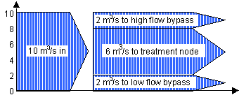
The Low and High Flow Bypasses are assumed to occur simultaneously. So for a Low Flow Bypass of 2m3/s, a High Flow Bypass of 8m3/s, and inflow of 10m3/s:
Individual Tank Properties
First, specify the number of rainwater tanks. Then, use button to set up the properties of the individual rainwater tanks. Note that the Storage Properties and Outlet Properties parameters (listed below) you set up for the individual tanks are the same for the Total Tank Properties. Note that the maximum number of tanks that can be added is 10,000.
Storage Properties
The Storage Properties define the physical characteristics of the rainwater tank.
Volume below overflow pipe
Defines the volume in the tank, in kilolitres, below its overflow pipe.
Surface Area
Defines the surface area of the rainwater tank in m2.
Depth above overflow (metres)
Defines the depth of water above the overflow pipe, to the top of the tank (in metres). This allows an ‘extended detention depth’ of the tank to be simulated, so that, for example a ‘leaky tank’ can be simulated, to model the effect on peak flow attenuation. When the tank water level exceeds the maximum depth of the tank, it is assumed to overflow as an unlimited weir.
Initial Volume
This specifies the volume of the rainwater tank at time-step zero (or prior to the model run).
Outlet Properties
Overflow Pipe Diameter
Defines the diameter of the overflow pipe in millimetres.
Total Tank Properties
Here, you specify the combined properties of the rainwater tanks. The parameters listed here are same as for Individual Tank Properties (above).
Use Custom Outflow and Storage Relationship
A custom pipe flow, weir flow and storage relationship can be specified to represent custom outlet and storage configurations for rainwater tanks. The outflow relationships can either replace or add to the standard music outflows. More information on how to use the custom outflow and storage facility is available in the Custom Storage and Outflow section.
There is an option to re-use water from a rainwater tank using this button. Refer to Water Re-use from Treatment Nodes for further information.
Tip Box
Demand will only be met when there is available storage in the rainwater tank.
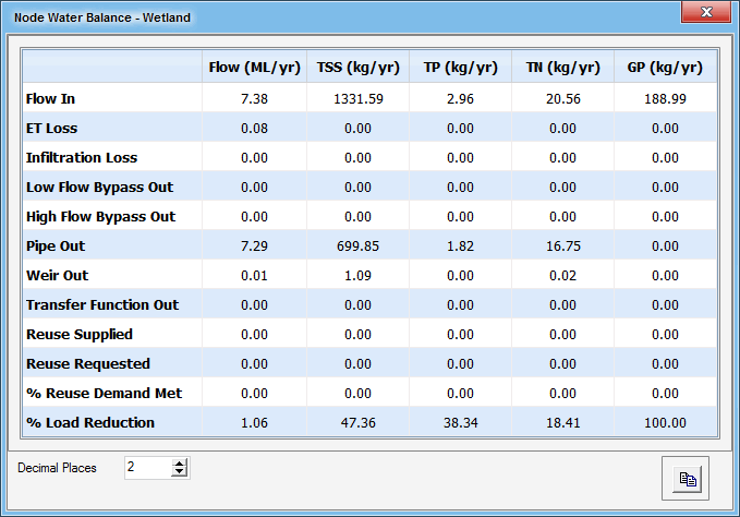
You can use the node water balance report to obtain basic information on the overall water balance at the rainwater tank, including basic information on reuse at the node. To do this, select node water balance from the list of available reporting boxes by right clicking on the node.
A reporting window will then be presented showing the water balances for various inflows and outflows at the rainwater tank as shown below.
The button can also be used to save data on the water re-use demand and supply at every time-step should that be required (see below).
It is possible to record flux data for the rainwater tank:
Refer to Treatment Devices for more information about fluxes.
The Notes button allows you to record any important details or assumptions for the pond or sedimentation basin (for example, you may provide an explanation of how the volume was calculated, or how the notional detention time was selected). It is good practice to provide notes of any important assumptions, for future reference by others using the model.
Advanced Rainwater Tank Properties
The advanced properties section (opened using the button) of the rainwater tank displays the parameters that describe the hydraulic characteristics for the tank, and the parameters that describe the treatment process in the rainwater tank.
Orifice Discharge Coefficient
The overflow outlet from the tank is modelled as a circular orifice with an invert located at the overflow level. Although a default value of 0.6 is adopted in the model, you can set any appropriate value between 0 and 1 (more information is available from most hydraulics text books).
Number of CSTR Cells
An infinite number of CSTRs would replicate the effects of plug flow through the rainwater tank. music defaults to two CSTR cells for the rainwater tank, however, as the shape of the system can vary markedly dependent on design, the number of CSTR cells that is required to represent the hydraulic efficiency of the design is dependent on that shape. Refer to Treatment Devices for details on configuring it.
Note that C** values do not apply to rainwater tanks.
Threshold Hydraulic Loading for C**
Does not apply to rainwater tanks.


