Note: This is documentation for version 4.11 of Source. For a different version of Source, select the relevant space by using the Spaces menu in the toolbar above
Splitter node - SRG
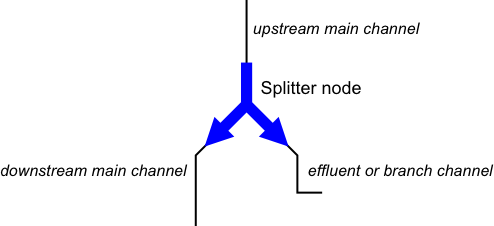
The controlled splitter is used to model the processes that take place when a stream divides into two. The controlled splitter has one inflow which is the upstream channel, and two outflows; the main channel and the effluent (Figure 1).
Figure 1. The controlled splitter node
Splitters come in three different varieties:
- The Controlled Splitter: The controlled splitter is characterised by the presence of some form of structure on the effluent that can be adjusted in response to the flows coming from upstream.
- The Uncontrolled Splitter: The uncontrolled splitter has no structure on its effluent and as a result the flows leaving the splitter downstream are a fixed function of the upstream flow rate.
- The Loss: If the effluent branch is not connected to anything the water flowing out the effluent branch will leave the model and appear to be a flow rate related loss.
This section describes how the controlled splitter node works in the flow phase and ordering phase in Source. More information relevant to how the controlled splitter node works in the ordering phase is provided in the Rules-Based Ordering - SRG entry.
Scale
The controlled splitter node, in common with all others, represents a location and can therefore be considered to be site scale. It is used at every model time-step.
Principal developer
eWate
Scientific provenance
Similar types of functionality exist in industry models such as IQQM, REALM and MSM_BigMod. As part of these models, the theory has been extensively tested over 30 years. The splitter functionality replicates that currently provided in IQQM, REALM and MSM_BigMod.
Version
Source v4.3
Dependencies
The controlled splitter node requires at least one node upstream. The controlled splitter node also requires at least one node downstream on the main channel, and the controlled splitter and uncontrolled splitter require at least one node downstream on the effluent channel as well.
Parameterisation of the splitter model
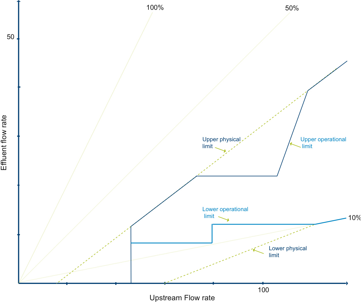
The splitter model consists of a functional relationship between the rate at which water arrives from upstream and the rate at which water will flow down the effluent. The physical properties of the splitter are modelled by using two curves (see Figure 2). The upper physical limit curve defines the maximum flow rate that can be sent down the effluent for a given upstream inflow. Likewise, the lower physical limit curve represents the minimum flow rate that must be sent down the effluent at the given upstream inflow rate.
Figure 2. Parameterisation of the splitter model
These two curves have the following properties:
- The lower physical limit must be always less than or equal to the upper physical limit.
- The curves cannot have a slope that is flat or decreasing at any point. The basic assumption is that any extra upstream flow will result in at least some more water going, or being able to go, down the effluent.
- Likewise for the main channel, an increase in the upstream flow rate is going to result in an increase in the possible main channel flow rate. As a result the curves must always have a slope less than one. This limit also means that the effluent outflow rate is less than the upstream inflow rate.
- The curves have to start with points having zero effluent flow.
- Having defined the envelope of physically plausible operation of the splitter the envelope of allowable operation can then be defined. The operational envelope may be a subset of the physical envelope (see Figure 2). The upper bound of the operational envelope may be lower than the physical one because the operators are limited by downstream flooding on the effluent for example. Similarly the lower boundary of the operational envelope may be higher than the physical boundary due to operational policies such as environmental requirements. The two curves that define this operational envelope have the following properties:
- They are always within the envelope defined by the two physical limit curves.
- The lower operational limit is no more than the upper operational limit at all points of the curves.
- The slope of the curves is steeper than flat but less than vertical. These limits are enforced so that every value of upstream inflow has a uniquely corresponding effluent outflow value on the curves and vice versa.
- The curves have to start with points having zero effluent flow.
The two operational limit curves are input by the modeller to model a loss, effluent, or distributary. The physical limit curves are only used to define the maximum extent of the operational envelope, and they do not need to be input. Note that for an uncontrolled splitter or loss the two curves would coincide.
The modeller can also dynamically operate the regulator on the controlled splitter each time-step, independently of the ordering system by defining the percentage opening of the regulator via the function manager. The user defines a % value between 0% and 100%, where 0% represents the regulator being fully operational between the lower operation limit and the upper operational limit.
A value of 100% represents the regulator being removed so that the lower operation limit equals the upper operational limit and there is no regulation capability on the controlled splitter. For percentage values greater than 0% the following equation is used to alter the lower operational limit curve each time-step.
| Equation 1 | MinEffluentFunction( x) = Min(MaxEffluentFunction( x), MinEffluentFunction( x) + RegulatorOpening * (MaxEffluentFunction( x) - MinEffluentFunction( x))) |
|---|
This functionality allows the modeller to control flow down effluents where orders may not be passed and will also work in conjunction with orders if they exist on the effluent.
Flow phase
During the flow phase there are five steps which must be carried out:
- Calculate how much water to put down the effluent branch
- In light of the answer obtained in the previous step, adjust the orders on the main channel and effluent if there is a shortfall in the amount of water that has arrived from upstream. This will also include recalculating the excess upstream requirements and repeating the process used in the ordering phase to assign this extra requirement to the correct owners (see the Ownership - SRG for more information about owners and ownership)
- Calculate any Murray-Style losses
- Carry out a borrowing process to transfer water to those owners that have a shortfall in upstream flow from those owners with an excess
- Having dealt with the allocated flow, apportion the unallocated flows going down the main channel and the effluent to the appropriate owners.
These steps are discussed further below.
Allotting the upstream flow between the main channel and the effluent
When deciding how much water to send down the effluent there are three points to consider:
- If there is a shortage of water arriving from upstream (that is when compared with the total orders that were made for this time step) then the aim is to try and deliver the same proportion of the effluent orders as those of the main channel. For example, if only 80% of the expected water arrives then the aim will be to meet 80% of the requirements on the main channel and the effluent
- If more water turns up than expected then no more water should be put down the effluent than was ordered
- It is necessary to stay within the operational envelope.
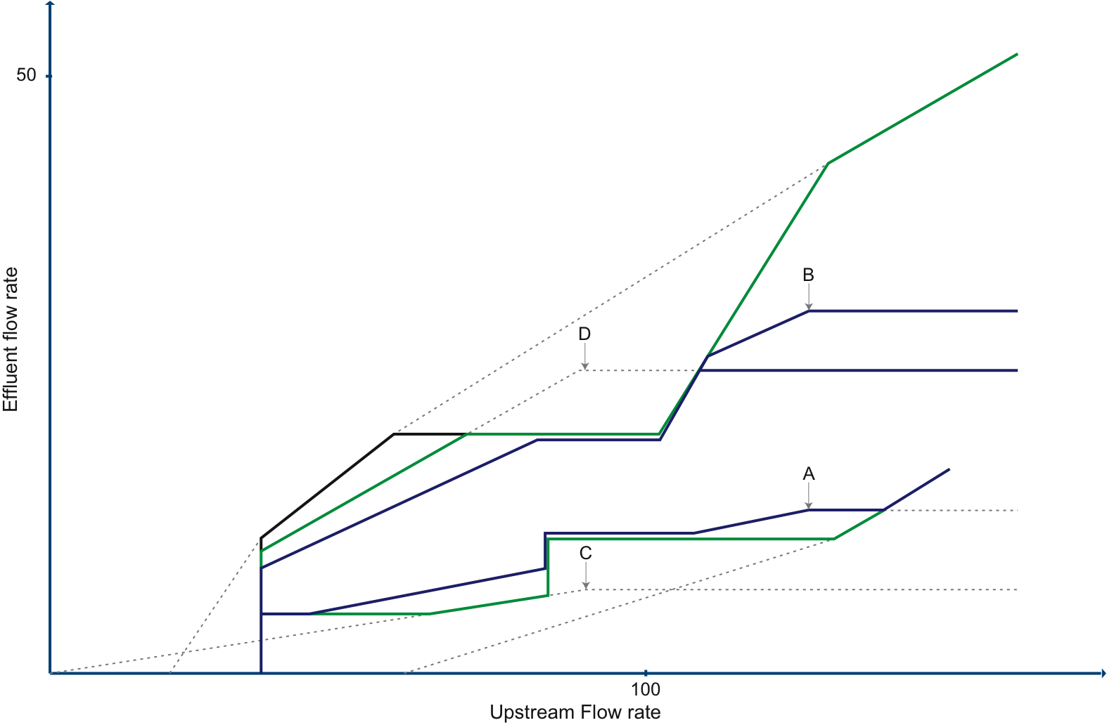
These three constraints can be illustrated graphically by plotting two examples on the chart of the splitter’s operational limits (Figure 3). At the end of the order phase, prior to the current time step’s flow phase, the final values of the upstream, main channel and effluent orders to be used during the flow phase would have been calculated. Plotted on Figure 3 are two sets of {Main channel order + Effluent order, Effluent order} (A and B) that fall within the operational envelope. Also plotted on Figure 3 are two cases (C and D) where the final balance of main channel and effluent orders resulted in an excess upstream requirement as shown by the fact that they fall outside the operational envelope.
Figure 3. Allocating the upstream flow between the main channel and the effluent
For each point a curve can be constructed by projecting a line back towards the origin and horizontally to the right. After adjusting each curve to fit within the operational envelope there is a set of curves (in blue for A and B, in green for C and D) from which the required effluent flow for the current upstream flow can be obtained.
Recalculating and attributing the excess upstream requirement
If less water arrived at the splitter than the final upstream requirement calculated in the ordering phase, the upstream and downstream requirements have to be recalculated based on how much water is now available. This is done by:
- Reducing the orders on the main channel and effluent so that they are equal to the flows that can be obtained with the current upstream inflow. Each owner is treated equally so if, for example, only 75% of the water planned for can be put down the effluent then each owners’ orders on the effluent would be reduced by 25%
- Now having an updated set of downstream requirements the process used in the ordering phase is repeated to calculate a revised upstream requirement for each owner including any excess upstream requirement they may be required to fund.
Calculate any Murray-style losses
If the splitter is using the Murray-style loss option, any excess upstream requirement would have already been shared to each owner using the fixed user-specified ratios. It is now necessary to work out who has to pay for any unwanted water flowing out the effluent. This is done by:
- Calculating each owner’s upstream flow threshold by multiplying the upstream flow threshold by the owner’s fixed ratio
- Calculate what effluent flow corresponds to the upstream flow threshold using the lower operational curve.
- For the effluent flows above the effluent downstream requirements but below the threshold identified at step 2, these are shared out to owners based on the fixed ratios
- If there is remaining effluent flow, this is shared out to owners in proportion to how far it is above their upstream flow threshold calculated at step 1. So, for example, if there are two owners, one 200 ML/d and the other 100 ML/d above their respective upstream flow thresholds, two thirds of the remaining effluent flow belongs to the first owner and one third to the second owner.
- When calculating the ownership of the water going out the effluent, the water identified as belonging to each owner is added to their respective upstream requirement. This enables owners without enough upstream flow to meet their share of the effluent flow to borrow water from the other owners.
Borrowing to make up shortfalls
At this point it is known how much allocated water (and water directed by the use of a Murray-Style loss) is going down the main channel and the effluent and the corresponding upstream flow requirement for each owner (including their share of the excess upstream requirement). It is now necessary to make sure that enough water has turned up for each owner. This is done by:
- Identifying all of the owners with upstream inflows that exceed their upstream requirements. These owners will become creditors to those owners we identify in the next step.
- Identify the owners with less upstream inflow than their upstream requirements. These owners will become debtors to the creditors identified in the previous step.
- Using the same borrowing process as that in the ordering phase, water is loaned to the debtors from the creditors.
- The creditors have their upstream requirements increased by the amount that they lend and likewise the debtors have theirs reduced by the amount they borrow. This is done so that at the final step of the flow phase the correct amount of unallocated upstream flow is identified.
Directing unallocated flows down the correct branch
The final step of the process is to direct the ownership of the unallocated flow down the correct branch. There are two options for how this is done:
- The unallocated flow going out the main channel and the effluent has the same ratio of ownership as the unallocated upstream flow. For example if the unallocated upstream inflow is 10:30:70 between three owners then the effluent and main channel will have unallocated flow in the same 10:30:70 ratio; or
- Having the unallocated flow going out as close as possible to a user-specified ratio as is achievable without borrowing water between owners.
Ordering phase
From the point of view of ordering, there are two aims that must be met:
- Enough water must be ordered to arrive from upstream at the splitter so that the orders downstream of the splitter on the main channel and effluent branches can be supplied; and
- If in meeting requirement 1 more water needs to be ordered from upstream than the sum of the downstream orders then it is necessary to work out who was responsible for this extra water and charge them for it (discussed in the section "Calculating and attributing excess requirement" below).
Collecting prior orders
The first step in the process is to go back and collate the orders that have already been made and are going to pass through the splitter at the same time as the orders now being considered. These orders have already been passed up the system as they are being delivered from a reservoir that is further upstream than the reservoirs being used to meet the orders being currently considered. This water may now be in transit or alternatively be sitting in a closer reservoir waiting to be released. As the correct case is unknown all the prior orders are treated as if they are in transit and cannot be modified.
Ensuring there will be enough water
Once the prior downstream orders have been collated the currently considered downstream orders can be added on to obtain the total downstream requirements on the main channel and effluent branch. If the value {Main channel order + Effluent order, Effluent order} is plotted on the chart of the splitter’s operational limits (Figure 1), the three possible outcomes are:
- The point lies above the envelope of operational limits: This indicates that the effluent order is too big in comparison with the main channel order and more water is going to have to be sent down the main channel than is currently required.
- The point lies within the envelope of operational limits: This indicates that both the effluent and main channel orders can be met.
- The point falls below the envelope of operational limits: This shows that the main channel order is too big in comparison with effluent orders and more water is going to have to be sent down the effluent.
For cases 1 and 3 the required upstream flow is determined by finding the closest point on the chart that falls inside the envelope of allowed operation. The next section describes how this is carried out. For case 2 the upstream order is simply the sum of the downstream orders.
Calculating and attributing excess upstream requirement
Firstly consider the situation where the effluent order is too big compared to the main channel order. In Figure 2 the point {Main channel order + Effluent order, Effluent order} has been plotted ("A") and it lies above the allowed envelope. To bring it back within the allowed envelope, the amount of water going down the main channel has to be increased until the point falls inside the envelope.
Graphically, this is represented by a line projecting horizontally to the right until the line intercepts the envelope at which point the required upstream flow will be found. The line is horizontal as it is only the main channel flows being increased, continuing until the combination of main channel and effluent flows falls within the envelope of allowed operation. The effluent flow remains unaltered. As the main channel flows had to be increased to enable orders on the effluent to be met, the users on the effluent are considered to have been responsible for the need for extra water so they will be required to fund it.
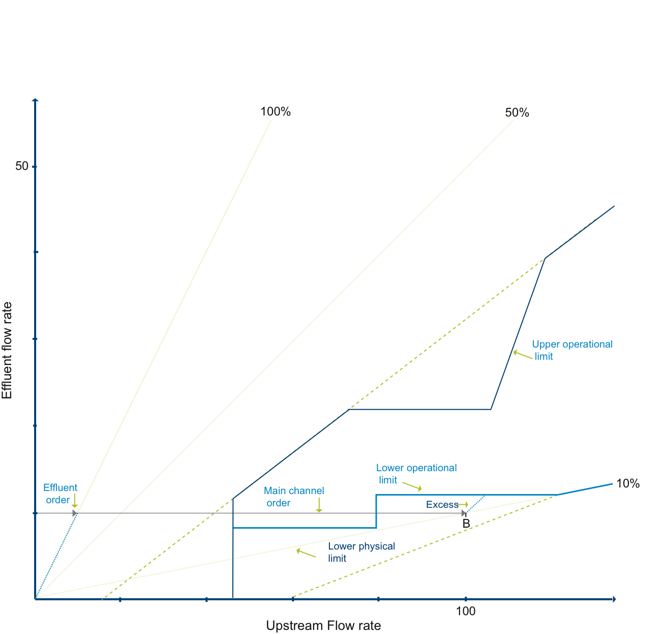
The second case is the situation where the effluent order is too small for the main channel order. This has been plotted in Figure 4 (point marked "B"). To remedy this situation more water has to be put down the effluent. As the main channel flow will remain the same the upstream flow will increase at the same rate as the effluent flow increases. On Figure 4 this will appear as a line projecting up to the right at a one-to-one slope and will intercept the lower edge of the envelope at the required upstream flow rate. In this case, while the excess water will be going down the effluent it is the main channel users who have to fund the excess required.
Figure 4. Situation when the main channel order is too big compared to the effluent order
In both cases the excess upstream flow requirement can then be calculated by subtracting from the required upstream flow the sum of the downstream orders.
Charging responsible parties for the excess requirement
Having now calculated the excess upstream requirements and identifying either the main channel or effluent water users as the cause, the appropriate users can now be charged for the extra water required to meet their orders. There are two ways the cost of the excess upstream requirement can be allocated:
- Based on the ratio of an owner’s order on the offending branch to all owners’ orders on that branch; or
- The Murray-Style Loss: The excess is shared amongst owners using defined ratios until the upstream flow exceeds a threshold. Above this threshold the excess is shared in proportion to how far above the threshold each owners’ flow is. It is assumed that the threshold is set above the range of regulated flows so only the sharing based on the fixed ratios is considered in the order phase.
By using either the fixed ratios or the current proportions, each owner’s share of the excess upstream requirement is added to their upstream requirement.
Adjusting the result in the light of prior orders
If there were any prior orders then the results have to be adjusted to take these into account. There are two steps involved in this adjustment:
- Adjusting each owner’s order to account for any change in the amount of excess flow considered necessary to meet the downstream requirements.
- Subtracting the prior orders from the order being passed up the system now.
As the total requirements on the main channel and effluent branch have changed it is possible that the excess which was calculated earlier in the model run as being applicable to the transit time now being considered has been reduced. This could have happened, as an example, if the users on one branch use a reservoir which is more distant than that of the users on the other. In this case, the users ordering first will generate an excess which, when the other users order can be then utilised to meet these new orders. The orders are adjusted as follows:
- All of the owners with more water in transit than they now require are identified.
- All of the owners that still need more water to meet their upstream flow requirement are found
- The water is loaned to the owners with remaining requirements by the owners that have a surplus. This is done by using the procedure described in the Borrow and Payback section in the chapter on Ownership.
- Creditor owners have their upstream flow requirement unaltered; debtor owners have their upstream requirements lowered by the amount that they have borrowed.
- Once the upstream flow requirements are adjusted for this borrowing, the order to pass up the system now is calculated by subtracting the prior orders. For creditor owners, their new orders will be zero as they already have more water in transit than they now need. For debtor owners, the new order will be for the extra upstream flow required that could not be sourced from other owners.
Input data
Refer to the Source User Guide for detailed data requirements and formats.
If the effluent is not regulated (i.e an Uncontrolled Splitter or a Loss) the user specifies a monotonically increasing piecewise linear function that describes the amount of flow that will pass down the effluent for corresponding upstream flow.
If the user specifies that the effluent is regulated (ie a Controlled Splitter) the user inputs monotonically increasing piecewise linear functions that describe the minimum and maximum amounts of flow that will pass down the effluent for corresponding upstream flow values.
The above mentioned functions may be entered manually by the user or by uploading comma separated files (.CSV).
Parameters or settings
Information on the meaning and function of each parameter, whether it is a "physical" parameter or otherwise, and its units can be found in the Theory and Process sections above. Where applicable, information on default values and the range of valid values can also be found in these sections.
Output data
Outputs include time series of outflows for the main channel and effluent channel.
Bibliography
Ladson, A.R. (2008) Hydrology: an Australian introduction. Oxford University Press, South Melbourne, Vic., Australia. 304 p. ISBN: 0195553586.
Loucks, D.P. and van Beek, E. (2005) Water resources systems planning and management: an introduction to methods, models and applications. UNESCO, Paris and WL | Delft Hydraulics, The Netherlands. 680 pp. ISBN 92-3-103998-9. Available at: ecommons.library.cornell.edu/handle/1813/2799.


