Note: This is documentation for version 5.0 of Source. For a different version of Source, select the relevant space by using the Spaces menu in the toolbar above
Water user node
Defining demand models
You can add a demand model to a water user node by right-clicking Demand Models and choosing the appropriate model from the contextual menu, as shown in Figure 1. When you add a new demand model, it is given a default name which is derived from the type of model. You can rename it by right-clicking the model and choosing Rename from the contextual menu.You can also add and configure multiple demand models on each water user node, but only one of the models can be active at a time. You can select which one should be the active model by choosing Set Active from the contextual menu.A model can be deleted by selecting it, then right-clicking and choosing Delete from the contextual menu. For each demand model type, you must enter the same type of information. In other words, you must specify distribution and on farm storages for every model type. These are described next.
Return flow (demand model)
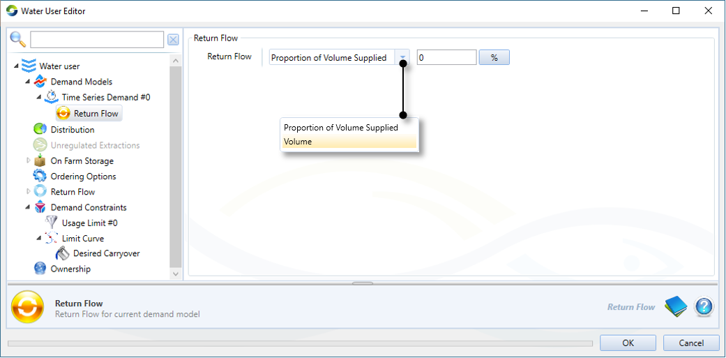
This refers to the amount of water that returns from the irrigated area back to the system, either to on farm storage (if enabled), directly. This could be irrigation runoff, rainfall runoff or return flows from a wetland. Access the return flow volume editor by adding a demand model, and expanding the demand model menu in the water user feature editor. For most models, the return flow volume is defined either as a percentage of the volume supplied to the demand model. These parameters are common for all the other demand models and can be defined by expanding the model and choosing Return flow (Figure 2). The Irrigator Demand model does not have a Return Flow menu item, but instead used the concept of return efficiency (see Irrigator user guide for further details).The IQQM model includes a number of parameters which determine the volume of return flow (IQQM crop demand model 2).
Figure 2. Water User Node, Demand (Return flow)
Demand distribution
Select Distribution to specify how water is supplied to the water user. This is important when the water user:
- is connected to multiple supply points; and/or
- has a choice of accounts against which orders can be placed.
There are two settings available: Non-Account Sharing (this is the default) and Account Sharing. Select the former if water distribution is undertaken in the absence of account. If the water user needs to place orders or extract water via accounts, select Account Sharing. Note that this is only available if a resource assessment system has been defined (refer to Resource assessment).
Non-account sharing
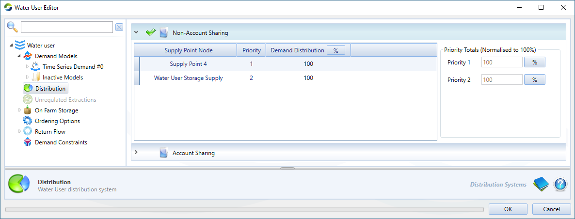
This is used when accounting is not required in the model. It specifies what proportion of orders and extractions should be assigned to each Supply Point node. If there is more than one supply point, you can define different priority levels for those points using the Priority parameter. Priority 1 is the highest level. All demand is assigned to supply points with priority 1 until the pumping capacity of those points is exhausted, after which priority 2 accounts are used, and so on. If there are multiple accounts at the same priority level, the Demand Distribution parameter (third column) defines how orders are distributed between those accounts. This defines the relative proportion of the water user’s order that should be assigned to the corresponding supply point. Lag times of all routing links upstream of the Supply Node are taken into consideration during the Demand Distribution process.
For elements with the same priority, the demand distribution sums to 100%; this is indicated on the right side of Figure 3. Note that these are normalised if they do not sum to 100%.
Figure 3. Water User node (Distribution, Non-Account Sharing)
Account sharing
This is used when the distribution of demand to supply points is governed by accounts. Choosing Account Sharing as the preferred distribution method will enable the Return Flow Recrediting tree menu item (shown in Figure 5). This parameter allows you to specify how much water is re-credited to accounts during the flow phase.
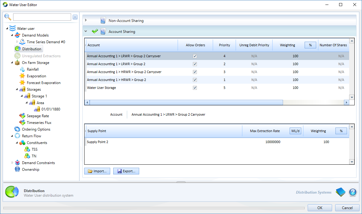
The first table in this dialog is the Account Distribution table, which shows how resources are distributed among all accounts. Choosing a particular account will populate the corresponding supply points in the second Supply Points table. It displays how water is shared amongst accounts at each supply point node. Table 1 explains the parameters that must be specified for these tables.
Figure 4. Water User node (Distribution, Account Sharing)
Table 1. Water User node, Distribution (Account sharing)
| Parameter | Type | Definition |
|---|---|---|
| Account Distribution table | ||
| Account | Populated automatically with names of the water user’s accounts. The links between the Water User node and its accounts can be created in the Resource Assessment Explorer. Refer to Resource assessment. When an account is created, it is, by default, added to the next priority level. Consider the example shown in Figure 4. If an account is added in this scenario, it will be assigned a Priority level of 4. | |
| Allow Orders | Allows you to switch the order of the account. The state of this parameter is determined by the Allow Orders parameter in a Supply point node, along with links to the water user node(s). If this is enabled, it lists the corresponding supply point nodes in the second table that have Allow Orders enabled in the node's feature editor. | |
| Priority | Controls the order in which demands are assigned to the various accounts. Priority 1 is the highest level. All demand is assigned to accounts at this level until the accounts are exhausted, after which priority 2 accounts are used, and so on. Accounts with a priority of N/A | |
| Unreg Debit Priority | The priority in which water is debited from accounts, with the lowest number having the highest priority. Its value is N/A when the Allow Orders checkbox is enabled. | |
| Weighting | % | Allows you to control the relative proportions of demand assigned to accounts at the same priority level. It follows on that if there is only one account in a priority level, this will be greyed-out. Also, if a new account is added, it is assigned a default weighting of 100. You are responsible for ensuring that ratios for each priority level sum to 100%. This column is populated automatically and is not editable. |
| Unit shares | ML | Displays the number of shares that the account has in the resource assessment system. This column is populated automatically and is not editable. |
| Debit Type | Indicates whether the account has been configured for Order or Use. | |
| Supply Points table | ||
| Max Extraction Rate | ML/d | Displays the maximum rate of extraction for the supply point. |
| Weighting | % | Shows the proportion of the account’s orders that have been assigned to this supply point. It has a default value of 100. Note that while Source evenly distributes the available pump capacity between all accounts which use that supply point, the extraction capacity is assigned to accounts based on priority level. For example, if there is only one account at priority level 1, then that account has full access to the pumping capacity of the supply point. |
Figure 5. Water User node (Return flow recrediting)
Simulating on-farm storages (OFS)
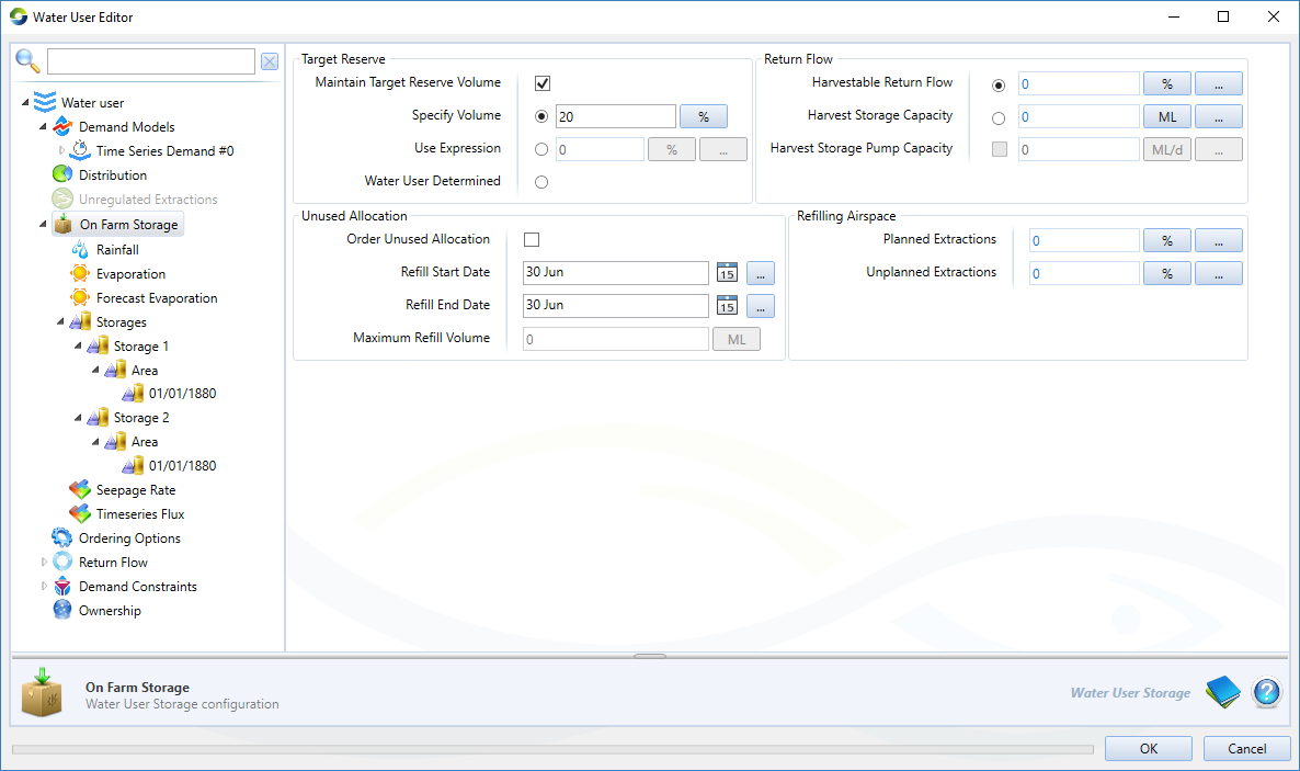
Right-click On Farm Storage and choose Enable to simulate on farm or other off-stream storages, which can be used to supply water to the demand model. There are a number of features to enable representation of the physical and management characteristics of these storages, for example:
- Filling from different water sources such as rainfall runoff harvesting, irrigation returns, harvesting of overbank (floodplain) flows as well as off-allocation and regulated water supplies.
- Maintenance of a reserve volume which can be used to supply the demand model in the case of shortfalls.
- A number of storages can be defined along with a separate filling and emptying priority
- Physical characteristics such as dead storage, surface area (and subsequently rainfall onto and evaporation from the surface) and seepage can be defined for each storage. Separate pump capacities can also be defined which governs the rate at which water can be pumped into a storage. The extraction rate from a storage is assumed to be unlimited.
The configuration parameters are illustrated in Figure 6 and summarised in Tables 2 to 5. Additional parameters relating to climate and physical characteristics of individual storages can be specified using the tree menu items as is further detailed below.
Figure 6. Water User node (on farm storage)
Table 2. Water User node (OFS, Target Reserve)
| Parameter | Type | Description |
|---|---|---|
| Maintain target reserve volume | Check to maintain the combined storage volume at the targeted reserve volume. Storages are filled in the specified filling order up to the target volume. If water in storage is below the target, no water will be made available to the demand model unless there is a shortfall in delivering ordered water. Water that is available to order is considered to be above the target reserve. During regular operation, the water user will not plan extractions from the OFS to meet demand that will take it below the target reserve. | |
| Options |
|
Table 3. Water User node (OFS, Unused Allocation)
| Parameter | Type | Description |
|---|---|---|
| Order Unused Allocation | ||
| Refill Date (Start and End) | Date | Set the limits of the refilling period using the Refill Start Date and Refill End Date fields. For example:
Within each date-of-refill field, you can perform the following actions:
|
| Maximum Refill Volume | Volume |
Table 4. Water User node (OFS, Return flow)
| Parameter | Type | Description |
|---|---|---|
| Harvestable Return Flow | ||
| Harvest Storage Capacity | Represents the volume of water that can be kept in the drainage system and can be pumped into an OFS. This can have inflow to the OFS even after rain stops, IF Pump Capacity is less than this parameter. |
Table 5. Water User node (OFS, Refilling Airspace).
Parameter | Type | Description |
|---|---|---|
Planned Extractions | % | The percentage of storage capacity which will be retained as airspace when filling the storage during the Refill Start Date and Refill End Date.
|
Unplanned Extractions | % | The percentage of storage capacity which will be retained when filling the storage with overbank, off Allocation, or regulated water. This airspace is also used to limit Off Allocation requests from the storage.
|
Climate data
You can supply climate data to the water user storage model with the following items in the list:
Rainfall is used to specify rainfall during the flow distribution phase. This can be defined as a single constant value, a time series, or as a function;
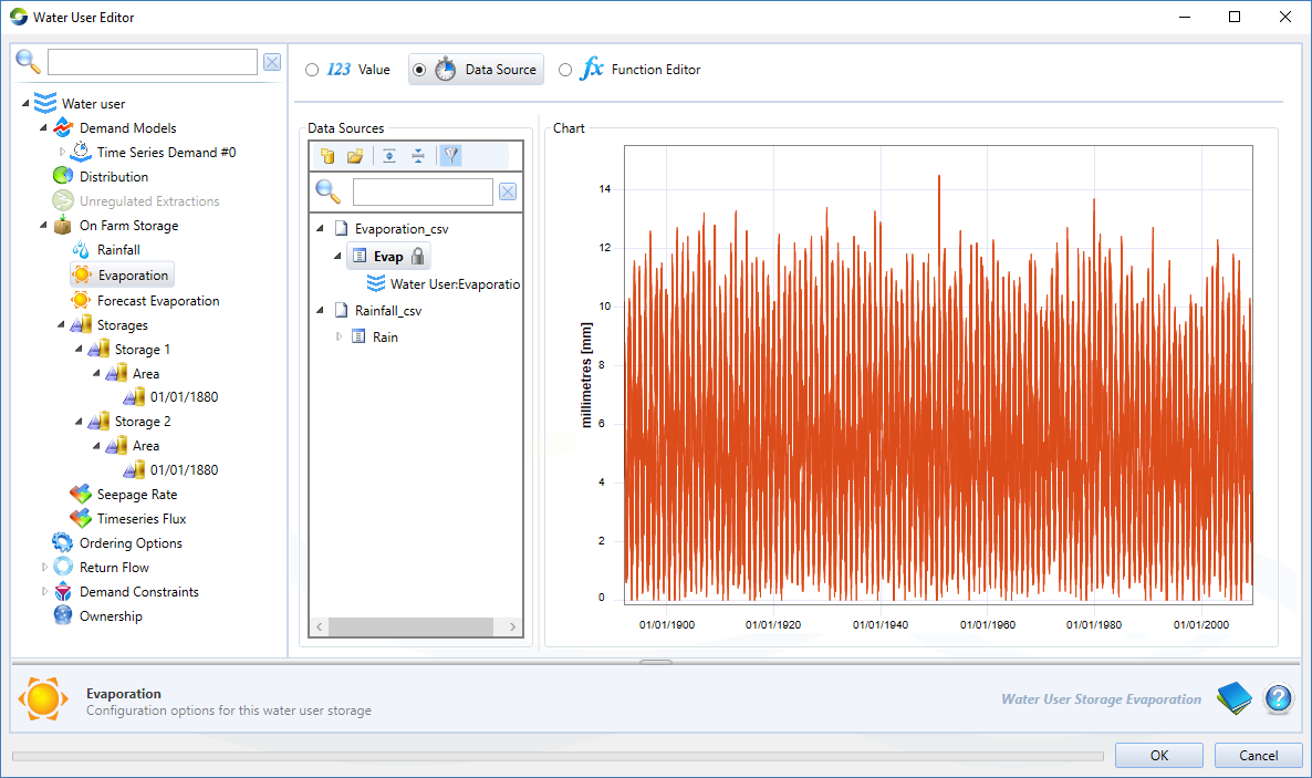
Evaporation (Figure 7) is used to specify the evaporation rate to be applied during the flow distribution phase. This can be defined as a single constant value, a time series, or as a function; and
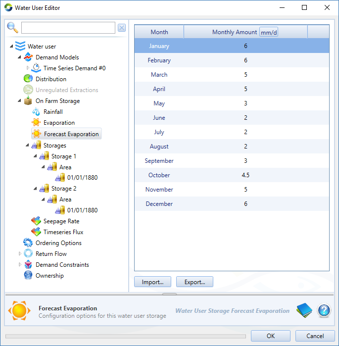
Forecast Evaporation (Figure 8) is used to define the evaporation rate to be assumed during the order phase as the model calculates the orders required to fill the storage.
Figure 7. Water User node (Storage, Evaporation)
Figure 8. Water User node (Storage, Forecast Evaporation)
Storages
If multiple storages are defined at a water user, the filling and emptying order can be specified by selecting the Storages item on the tree menu.
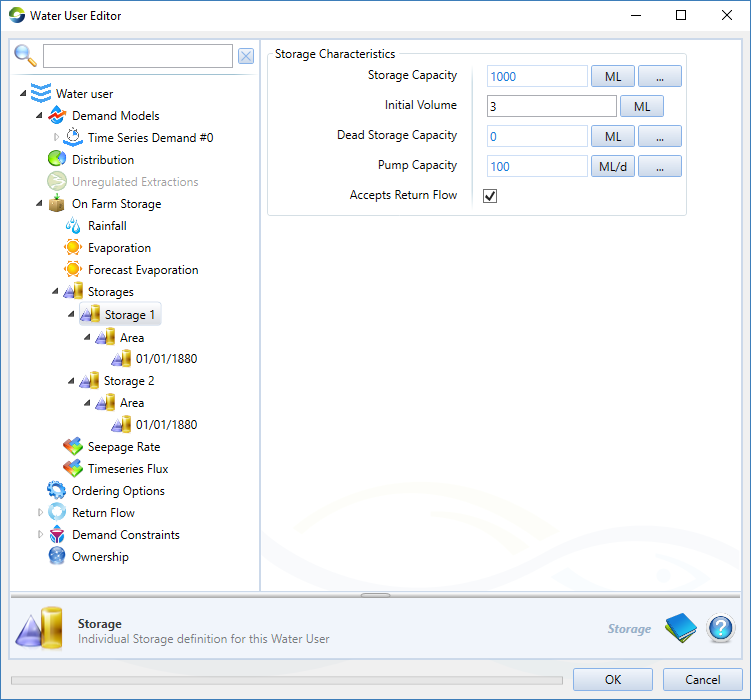
The model is initialised with a single storage; to add additional storages right-click Storages and choose Add On Farm Storage. Click on each storage name to specify Storage Characteristics as shown in Figure 9. Note that Pump Capacity governs the rate at which water can be pumped into a storage. The extraction rate from a storage is assumed to be unlimited.
Figure 9. Water User node (Storage, Individual Storage Characteristics)
Area
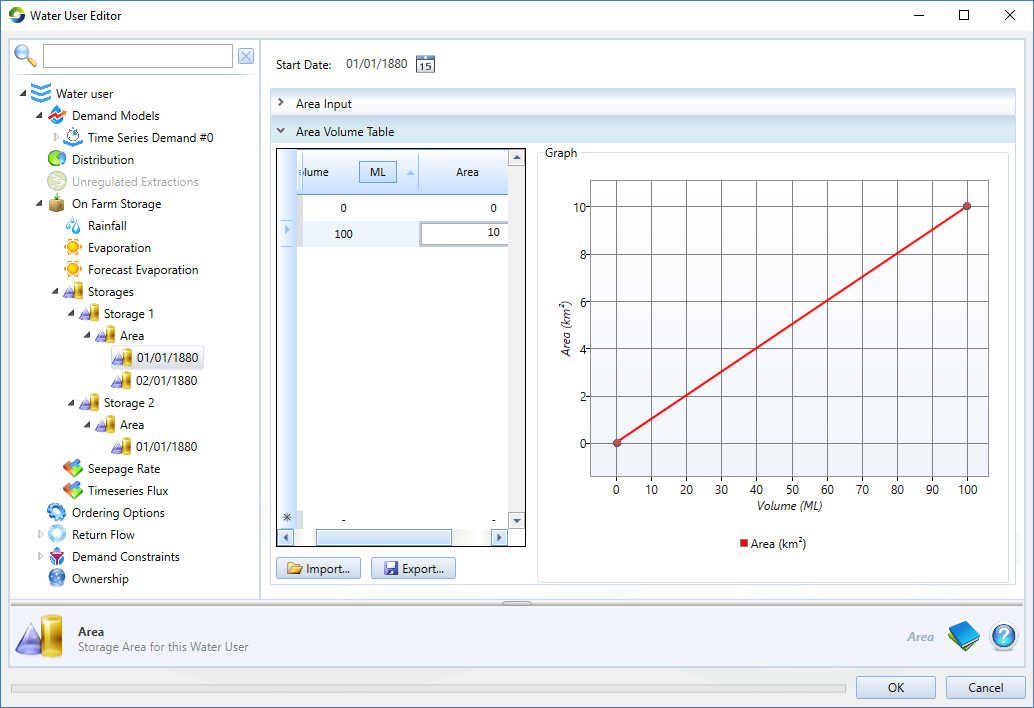
For each individual storage, you can specify the surface area, either as a constant or through a volume – area relationship as illustrated in Figure 8. If the area relationship changes over time, this can be specified by adding additional area values: right-click Area and choose Add Water User Storage Area. Each area relationship has a Start Date as illustrated in Figure 10.
Figure 10. Water User node (Storage, Area)
Seepage Rate
It is assumed that all storages have the same seepage rate. This can be specified as either a constant rate or as a rate varying with volume.
Timeseries Flux
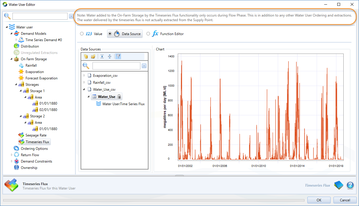
Timeseries flux may be applied directly to an on farm storage using either a value, data source or a function (See Figure 11 below). It is assumed to be applied to the storages according to the filling priority order. This flux is intended to be used for calibration purposes only and has a number of specific assumptions. The intention is to be able to supply the demand model with a known quantity of water without affecting other processes that occur at the Supply Point, such as ordering. The following assumptions must be noted:
- Water that spills as a result of the Timeseries Flux is ignored. The spilled water does not appear in the spilled volume or the return flow and a Warning will appear in the Log Reporter if the on farm storage spills.
- The Timeseries Flux is applied at flow phase and is not accounted for in the ordering phase.
- The water is added after rainfall and evaporation, so will not contribute to the volume change when calculating surface area to apply rainfall and evaporation.
- The water is added before the demand model extracts water for the time step and is not part of the extracted water.
- Timeseries Flux will be applied ignoring airspace requirements and will fill the storage to capacity
- The functionality is available in both:
- Water User Node Model; and
- Agricultural Runoff Rainfall Runoff Model
Figure 11. Water User node (Storage, Timeseries Flux)
Ordering Options
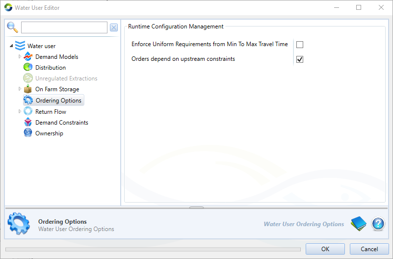
Configure ordering options for the water user, as shown in Figure 12 and described in Table 6.
Figure 12. Water User node (Ordering Options)
Table 6 Water User, Ordering Options.
Parameter | Type | Description |
|---|---|---|
Enforce Uniform Requirements from Min and Max Travel Time | When modelling long reaches with a number of links and supply points with travel time between them, it is possible to link a single water user to several supply points. When this checkbox is ticked, you will ensure the water user takes the same amount of water from each supply point on each time step. If not selected, it will be affected by orders that change between minimum and maximum travel time. | |
Orders Depend on Upstream Constraints | This checkbox changes the sequence in which constraints and water user orders are processed. Usually, Water User orders are calculated at the start of the time step (although they are not 'sent up' until the ordering phase). With this option turned on, the water users orders is calculated after the constraints upstream from the connected supply points, but before the supply point constraints. |
Return Flow (routing)
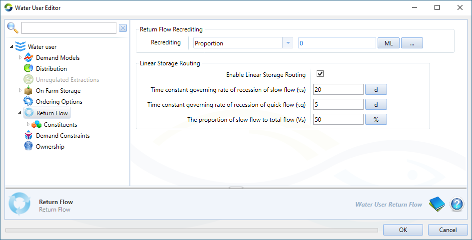
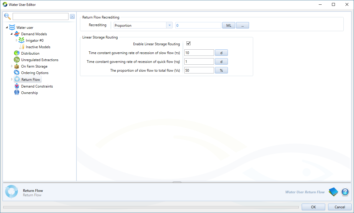
If a link is present downstream from the water user node connecting it back to the river system, the return flow volume generated within the water user demand model can be routed back to the confluence using linear storage routing. If Enable Linear Storage Routing is toggled on, a routing method is applied to attenuate the return flow and better reflect the discharge of water from the water user over time.
Figure 13. Water user (Return Flow)
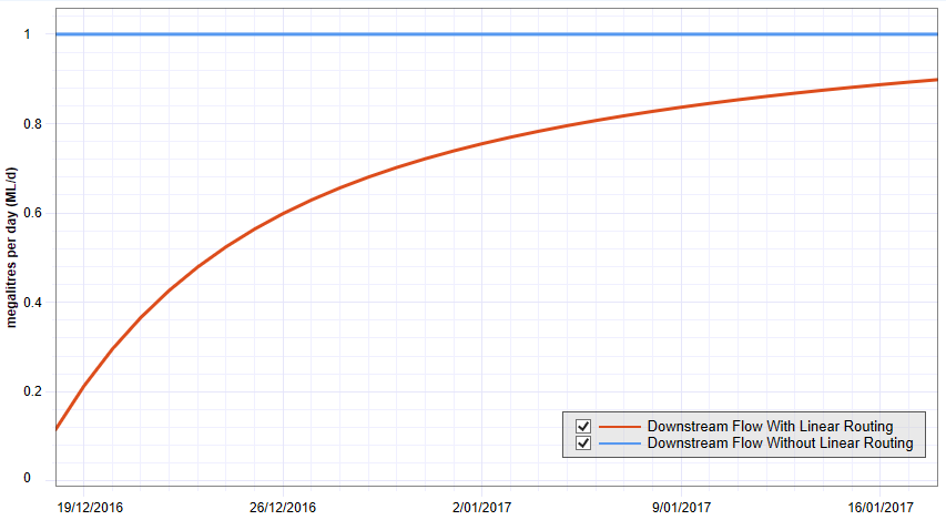
The Downstream Return Flow recorder and Downstream Flow for the water user will reflect the differences between a model run with and without linear storage routing applied, and the water received by the downstream link. For more information on how to configure the linear storage routing, please see IHACRES CMD - Storage Routing
Figure 14. Downstream Flow with and without Linear Routing enabled
Demand constraints
Using demand constraints, you can add limit curves and usage limits to demand models (using the contextual menus shown in Figure 1).
Limit curve
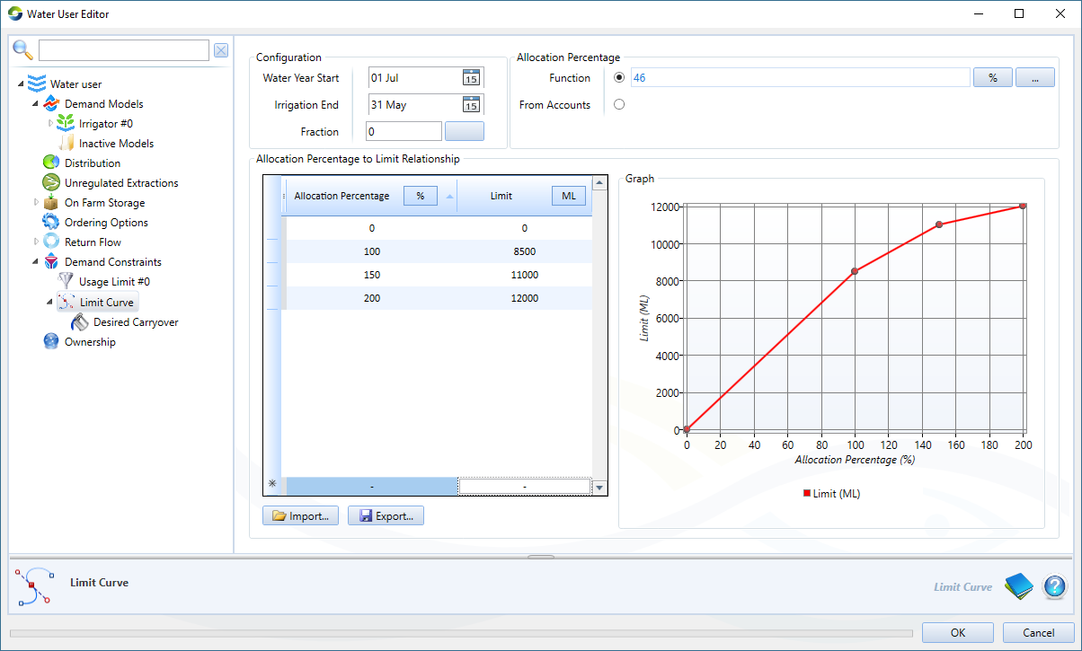
A limit curve defines the maximum cumulative demand allowable over an irrigation season, which in turn will limit the volume of water ordered each time step. It can be used to prevent a demand node from using too much of its available allocation early in the water year. Limit curves are intended for use with annual accounting resource assessment systems. Source calculates the limit curve based on a number of user-defined parameters, including a piecewise linear relationship table relating allocation percentage to limits (see configuration window, Figure 15.)
To create a limit curve, right click Demand Constraints and choose Add Limit Curve from the contextual menu.
Specify the dates for Water Year Start and Irrigation End.
Fraction represents a proportion (0 – 1) which determines the coefficients a, b and c of the limit curve equation.
The Allocation Percentage is the available allocation in relation to the total entitlement for the accounts associated with this water user. If there are n account types, then each account receiving 100% of its entitlement will be expressed as an allocation percentage of n × 100%. An allocation percentage of 150% indicates that the highest reliability/security account has been allocated 100% of its entitlement, and the next highest reliability has been allocated 50% of its entitlement. It can be expressed in one of three ways:
As a constant by enabling the Function radio button and entering the desired value (as a percentage). Figure 15 shows an example where a constant has been specified for the Allocation Percentage;
Customised using a function to vary according to the allocation percent set up in a Resource Assessment System (once again, enable the Function radio button and click the ellipsis button to open the Function Editor); or
Enable the From Accounts radio button to allocate the percentage using the allocations defined for each account associated with this water user.
The Allocation percentage to Limit relationship table will be used to look up limits based on the allocation percentage specified at each time step. It will also be used to calculate an adjusted allocation percentage if there is carryover.
Refer to Water user node SRG - Limit Curves for more details on how limit curves are implemented. To view the calculated limit curve, enable the cumulative demand recorder.
Figure 15. Water user (Demand constraints, Limit curves)
Desired carryover
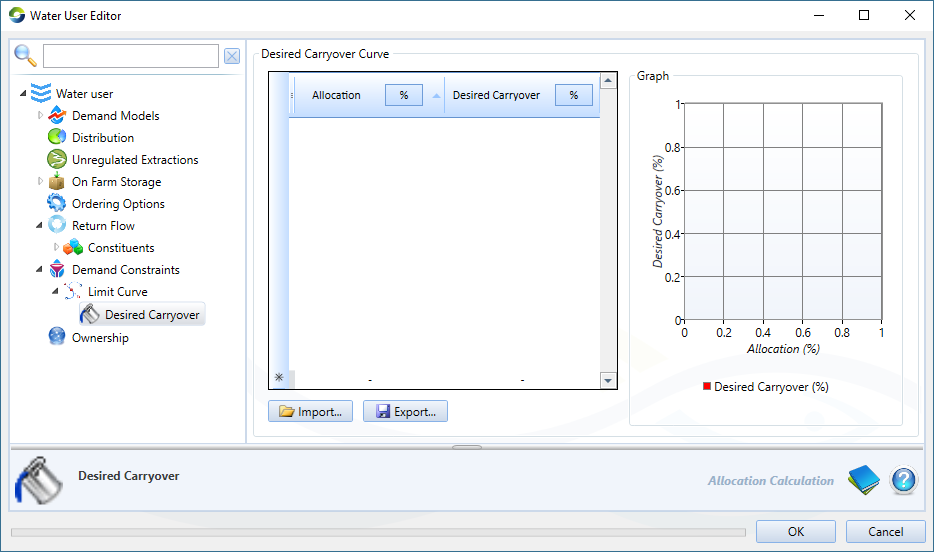
This is the total volume of unused water to be carried over at the end of the irrigation season to the next season, given the allocation percentage in the current time step. The Desired Carryover Curve is specified by the user (Figure 16) and is used to calculate an additional volume to be withheld when calculating the adjusted limit, given an Allocation percentage. In this case, the value looked up in the table for allocation percentage will be the adjusted percentage after carryover and spillable water have been taken into consideration. Desired carryover is expressed as a percentage of the account host's total allocation for the water year. Refer to the Source Scientific Reference Guide for more details on how Desired Carryover is implemented.
Figure 16. Water user (Demand constraints, Limit curves, Carryover)
Usage limits
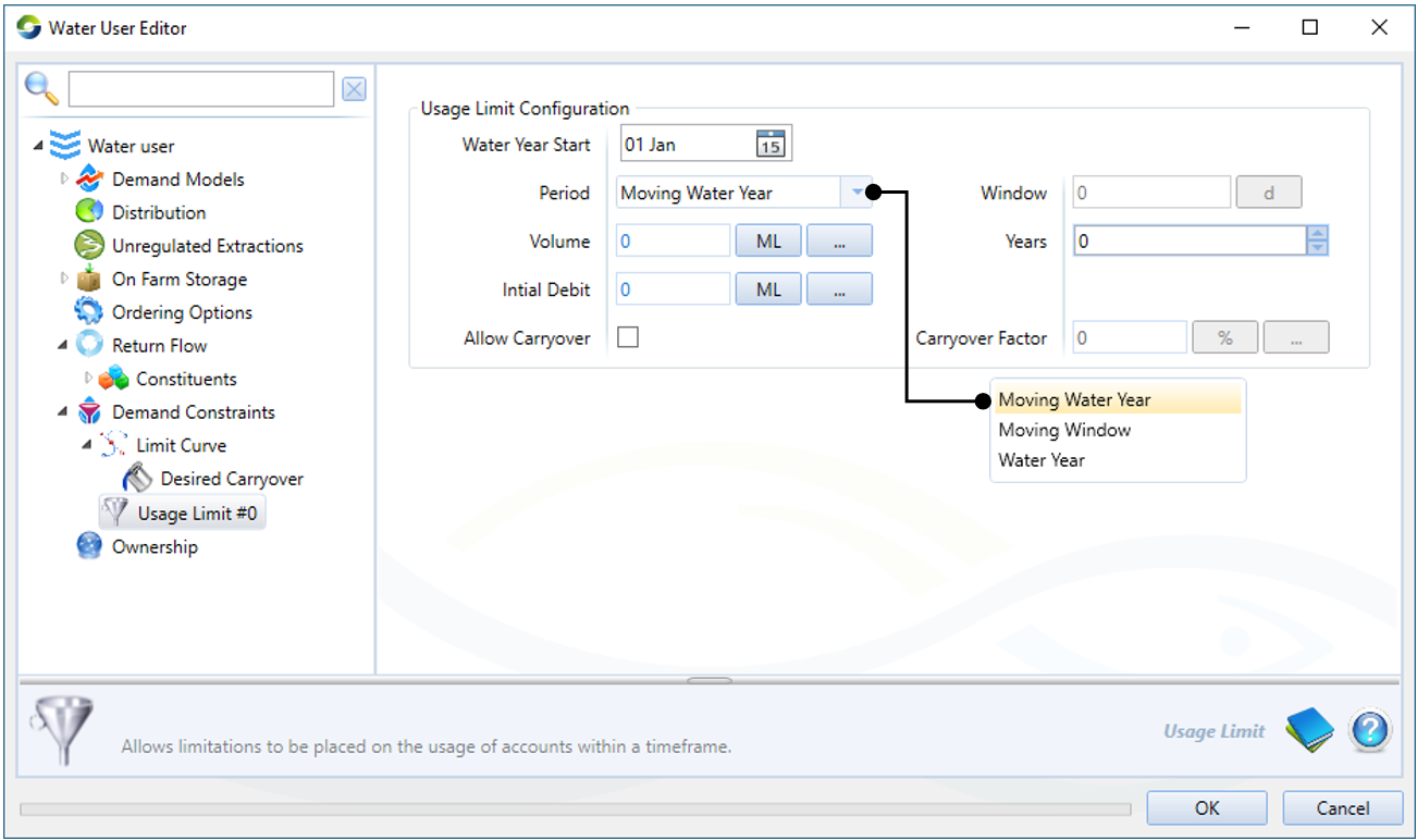
Here, you can add limits on account usage for a specified time period.
Figure 17. Water User (Demand constraints, Usage limit)
Configuring Time Period
There are three options for configuring time period. These are the periods during which the cumulative usage is accounted for.
- Water Year - For this option select Water Year in the Period dropdown, select a Water Year Start date and a number of years (X) in the Years field. This will account for the cumulative usage in X number of whole water years starting at the selected start date. After X Water Years the account resets.
- Moving Water Year - For this option select Moving Water Year in the Period dropdown, select a Water Year Start date and a number of years (X) in the Years field. In each water year, the cumulative use of the previous X number of water years from the start date is accounted for. At the start of each water year, there is a change in which years are within this water year window.
- Moving Window - For this option select Moving Window in the Period dropdown and a time period (Y) and a time step (eg. days) in the Window field. This will account for the cumulative usage from Y time steps ago, and the account will reevaluate every model time step.
Configuring Usage Volume Limit
Enter a volume in the Volume field using either a value, data source or function. This is the basic volumetric limit of usage during the specified time period. The Water User may also have access to carryover, so the overall limit of usage for the Water User in the time period is the basic volumetric limit plus carryover.
Configuring Carryover
Carryover only applies to a Water Year time period and has no function for other time period types. To configure carryover tick the Allow Carryover checkbox and then enter a Carryover Factor. The Carryover Factor is the total account limit expressed as a percentage of the basic volumetric limit, so this percentage must be greater than or equal to 100% for carryover to occur. Unused account from the previous time period will be carried over, unreduced, to the next period up to the Carryover Factor limit. It may be entered as a value, data source or function.
The Water User Usage Limit will not work for a Water User that is attached to any unregulated Supply Points.
Ownership
You must enable ownership at the scenario level (using Edit » Ownership) prior to configuring ownership at the water user node. Refer to Ownership for more information.


