Water user node
The Water User node represents a point in the node-link network where demand is modelled. It is responsible for generating orders, managing water extractions, and providing drainage return flows. The node is divided into three components each accessible via the hierarchical list:
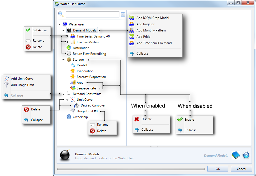
- Demand Models – forecasts water demand and provides return flow to account holders (Figure 1). Several types of models are available, including time-series demand, monthly pattern, crop models and environmental demand;
- Distribution – manages orders and extractions through accounts when resource assessment and accounting functions are enabled (Figure 3). A simple distribution system is also available for cases where accounting is not required; and
- Storage – manages water user storages such as on farm storages (OFS). Refer to Figure 4.
When uploading time-series files for any model, note that the data files do not stipulate units. Select the appropriate units in the feature editor using the Units: drop-down menu.
Figure 1. Water User node (model selection)
In Source, each water user node must be connected to at least one supply point node, but may be connected to more than one supply point node. Each supply point node to which a water user node is connected can supply water to the water user.
Defining demand models
You can add a demand model to a water user node by right-clicking Demand Models and choosing the appropriate model from the contextual menu, as shown in Figure 1.
When you add a new demand model, it is given a default name which is derived from the type of model. You can rename it by right-clicking the model and choosing Rename from the contextual menu.
You can also add and configure multiple demand models on each water user node, but only one of the models can be active at a time. You can select which one should be the active model by choosing Set Active from the contextual menu.
A model can be deleted by selecting it, then right-clicking and choosing Delete from the contextual menu. For each demand model type, you must enter the same type of information. In other words, you must specify distribution and on farm storages for every model type. These are described next.
Return flows
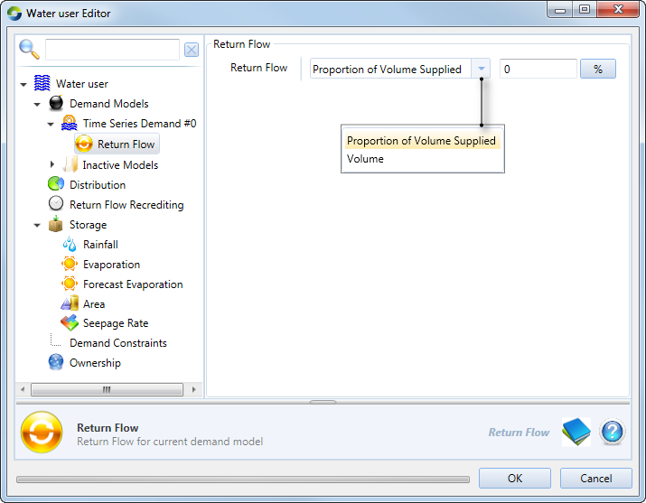
This refers to the amount of water that returns from the water user back to the system. This could be irrigation runoff, rainfall runoff or return flows from a wetland. Double-clicking the demand model enables the return flow editor. The IQQM model includes a number of parameters which determine the volume of return flow (IQQM crop demand model 2). For all other models, the return flow volume is defined either as a percentage of the volume supplied to the demand model. These parameters are common for all the other demand models and can be defined by expanding the model and choosing Return flow (Figure 2).
Figure 2. Water User Node, Demand (Return flow)
Demand distribution
Select Distribution to specify how water is supplied to the water user. This is important when the water user:
- is connected to multiple supply points; and/or
- has a choice of accounts against which orders can be placed.
There are two settings available: Non-Account Sharing (this is the default) and Account Sharing. Select the former if water distribution is undertaken in the absence of account. If the water user needs to place orders or extract water via accounts, select Account Sharing. Note that this is only available if a resource assessment system has been defined (refer to /wiki/spaces/SD37/pages/25559519).
Non-account sharing
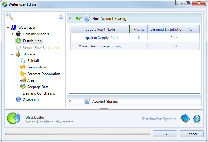
This is used when accounting is not required in the model. It specifies what proportion of orders and extractions should be assigned to each Supply Point node. If there is more than one supply point, you can define different priority levels for those points using the Priority parameter. Priority 1 is the highest level. All demand is assigned to supply points with priority 1 until the pumping capacity of those points is exhausted, after which priority 2 accounts are used, and so on. If there are multiple accounts at the same priority level, the Demand Distribution parameter (third column) defines how orders are distributed between those accounts. This defines the relative proportion of the water user’s order that should be assigned to the corresponding supply point. You are responsible for ensuring that for elements with the same priority, the demand distribution sums to 100%.
Figure 3. Water User node (Distribution, Non-Account Sharing)
Account sharing
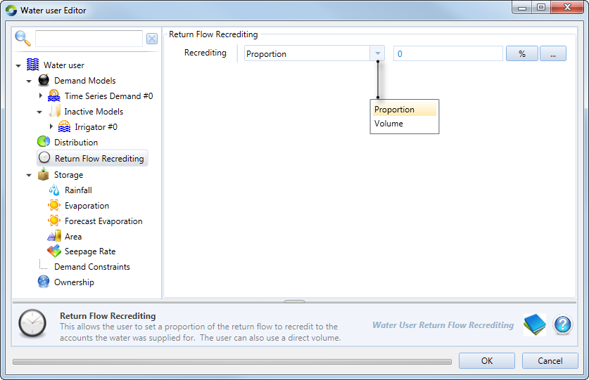
This is used when the distribution of demand to supply points is governed by accounts. Choosing Account Sharing as the preferred distribution method will enable the Return Flow Recrediting tree menu item (shown in Figure 5). This parameter allows you to specify how much water is recredited to accounts during the flow phase.
The first table in this dialog is the Account Distribution table, which shows how resources are distributed among all accounts. Choosing a particular account will populate the corresponding supply points in the second Supply Points table. It displays how water is shared amongst accounts at each supply point node. Table 1 explains the parameters that must be specified for these tables.
Figure 4. Water User node (Distribution, Account Sharing)
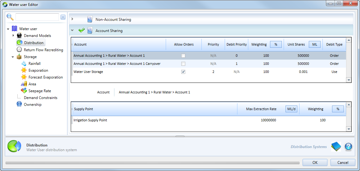
Table 1. Water User node, Distribution (Account sharing)
| Parameter | Type | Definition |
|---|---|---|
| Account Distribution table | ||
| Account | Populated automatically with names of the water user’s accounts. The links between the Water User node and its accounts can be created in the Resource Assessment Explorer. Refer to /wiki/spaces/SD37/pages/25559519. When an account is created, it is, by default, added to the next priority level. Consider the example shown in Figure 4. If an account is added in this scenario, it will be assigned a Priority level of 4. | |
| Allow Orders |  | Allows you to switch the order of the account. The state of this parameter is determined by the Allow Orders parameter in a Supply point node, along with links to the water user node(s). If this is enabled, it lists the corresponding supply point nodes in the second table that have Allow Orders enabled in the node's feature editor. |
| Priority | Controls the order in which demands are assigned to the various accounts. Priority 1 is the highest level. All demand is assigned to accounts at this level until the accounts are exhausted, after which priority 2 accounts are used, and so on. Accounts with a priority of N/A | |
| Debit Priority | Shows the priority in which water is debited from accounts, with the lowest number having the highest priority. Its value is N/A when the Allow Orders checkbox is enabled. | |
| Weighting | % | Allows you to control the relative proportions of demand assigned to accounts at the same priority level. It follows on that if there is only one account in a priority level, this will be greyed-out. Also, if a new account is added, it is assigned a default weighting of 100. You are responsible for ensuring that ratios for each priority level sum to 100%. This column is populated automatically and is not editable. |
| Unit shares | ML | Displays the number of shares that the account has in the resource assessment system. This column is populated automatically and is not editable. |
| Debit Type | Indicates whether the account has been configured for Order or Use. | |
| Supply Points table | ||
| Max Extraction Rate | ML/d | Displays the maximum rate of extraction for the supply point. |
| Weighting | % | Shows the proportion of the account’s orders that have been assigned to this supply point. It has a default value of 100. Note that while Source evenly distributes the available pump capacity between all accounts which use that supply point, the extraction capacity is assigned to accounts based on priority level. For example, if there is only one account at priority level 1, then that account has full access to the pumping capacity of the supply point. |
Figure 5. Water User node (Return flow recrediting)
Simulating on-farm storages (OFS)
Right-click Storage and choose Enable to simulate on farm or other off-stream storages, which can be used to supply demand to the model. Additionally, in case of any shortfalls in the demand model, the OFS can be used to source additional water (if it is available) to balance this shortage. These storages can also behave like an additional demand model within the Water User node. In this situation, the Water User node generates demand to fill the storage to the required level. The configuration parameters are summarised in Tables 2 and 3.
Figure 6. Water User node (on farm storage)
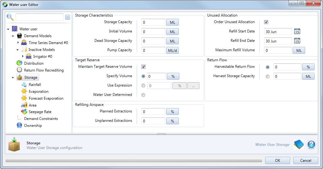
Under Storage Characteristics, enter the parameters for the on-farm storage, as shown in Figure 6. Note that Pump Capacity governs the rate at which water can be pumped into a storage. The extraction rate from a storage is assumed to be unlimited.
Table 2. Water User node (OFS, Target Reserve)
| Parameter | Type | Description |
|---|---|---|
| Maintain target reserve volume | | Check to maintain the storage at the targeted reserve volume. If storage is below the target, no water will be made available to the demand model unless there is a shortfall in delivering ordered water. Water that is available to order is considered to be above the target reserve. During regular operation, the water user will not plan extractions from the OFS to meet demand that will take it below the target reserve. |
| Options |  |
|
Table 3. Water User node (OFS, Refilling Airspace).
| Parameter | Type | Description |
|---|---|---|
| Planned Extractions | % | The percentage of storage capacity which will be retained as airspace when filling the storage during the Refill Start Date and Refill End Date. |
| Unplanned Extractions | % | The percentage of storage capacity which will be retained when filling the storage with overbank, off Allocation, or regulated water. This airspace is also used to limit Off Allocation requests from the storage. |
Table 4. Water User node (OFS, Unused Allocation)
| Parameter | Type | Description |
|---|---|---|
| Order Unused Allocation | | |
| Refill Date (Start and End) | Date | Set the limits of the refilling period using the Refill Start Date and Refill End Date fields. For example:
Within each date-of-refill field, you can perform the following actions:
|
| Maximum Refill Volume | Volume |
Table 5. Water User node (OFS, Return flow)
| Parameter | Type | Description |
|---|---|---|
| Harvestable Return Flow | | |
| Harvest Storage Capacity | Represents the volume of water that can be kept in the drainage system and can be pumped into an OFS. This can have inflow to the OFS even after rain stops, IF Pump Capacity is less than this parameter. |
Climate data
You can supply climate data to the water user storage model with the following items in the list:
- Evaporation (Figure 6) is used to specify the evaporation rate to be applied during the flow distribution phase. This can be defined as a single constant value, a time series, or as a function;
- Rainfall is used to specify rainfall during the flow distribution phase. The configuration window is similar to that for Evaporation; and
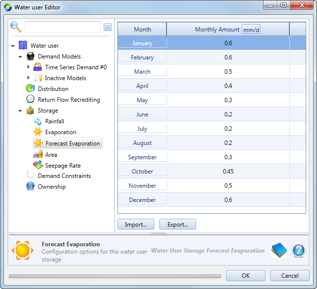
- Forecast Evaporation (Figure 7) is used to define the evaporation rate to be assumed during the order phase as the model calculates the orders required to fill the storage.
Figure 6. Water User node (Storage, Evaporation)
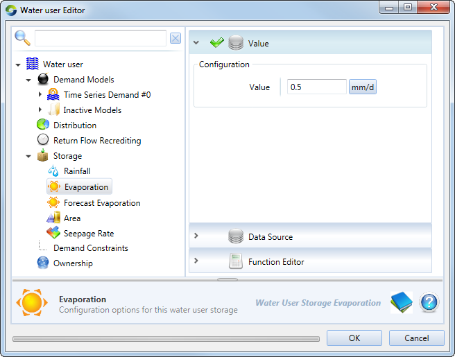
Figure 7. Water User node (Storage, Forecast Evaporation)
Area
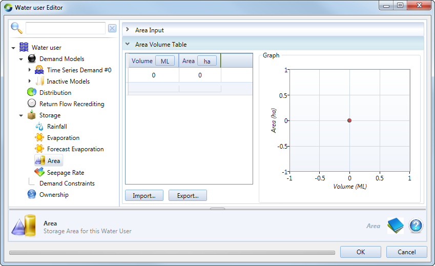
You can specify the area and seepage rate of the OFS using the tree menu items. Figure 8 shows the configuration window for Area.
Figure 8. Water User node (Storage, Area)
Demand constraints
Using demand constraints, you can add limit curves and usage limits to demand models (using the contextual menus shown in Figure 1).
Limit curve
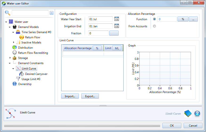
The limit curve configuration dialog (shown in Figure 9) prevents a demand node from using all of its available allocation too early in the season. It is defined based on a relationship between the announced or available allocation and limit.
Specify the dates for Water Year Start and Irrigation End. Fraction represents a proportion (0 – 1) which determines the coefficients a, b and c of the limit curve equation. Please see the Source Scientific Reference Guide for more details on how Fraction is implemented.
The Allocation Percentage is the percent per share entitlement of account type. It can be set up in one of three ways:
- As a constant by enabling the Function radio button and entering the desired value (as a proportion);
- Customised using a function to vary according to the allocation percent set up in a Resource Assessment (once again, enable the Function radio button and click the corresponding ellipsis button to open the Function Editor); or
- Enable the From Accounts radio button to
Figure 9. Water user (Demand constraints, Limit curves)
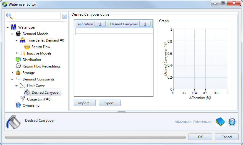
Desired carryover
This is the total volume of unused water to be carried over at end of the season to the next season.
Figure 10. Water user (Demand constraints, Limit curves, Carryover)
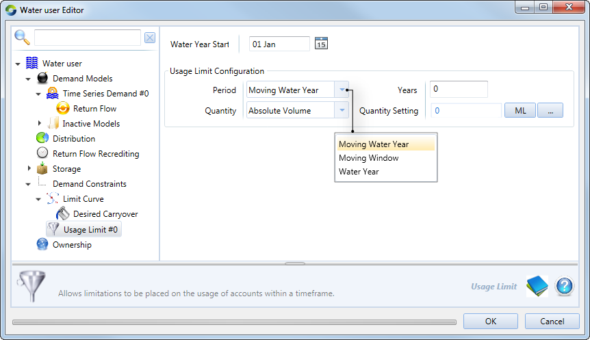
Usage limits
Figure 11. Water User (Demand constraints, Limit curves, Carryover)
Ownership
You must enable ownership at the scenario level (using Edit » Ownership) prior to configuring ownership at the water user node. Refer to Ownership for more information.