Schematic Editor
- asatheesh (Unlicensed)
The Schematic Editor allows you to create and manage an operations or schematic scenario.
Customising views in the Schematic Editor
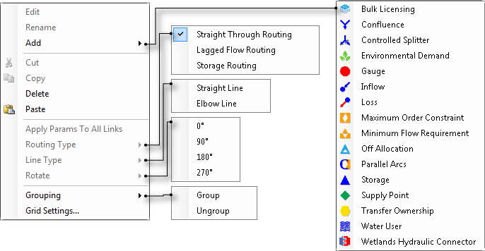
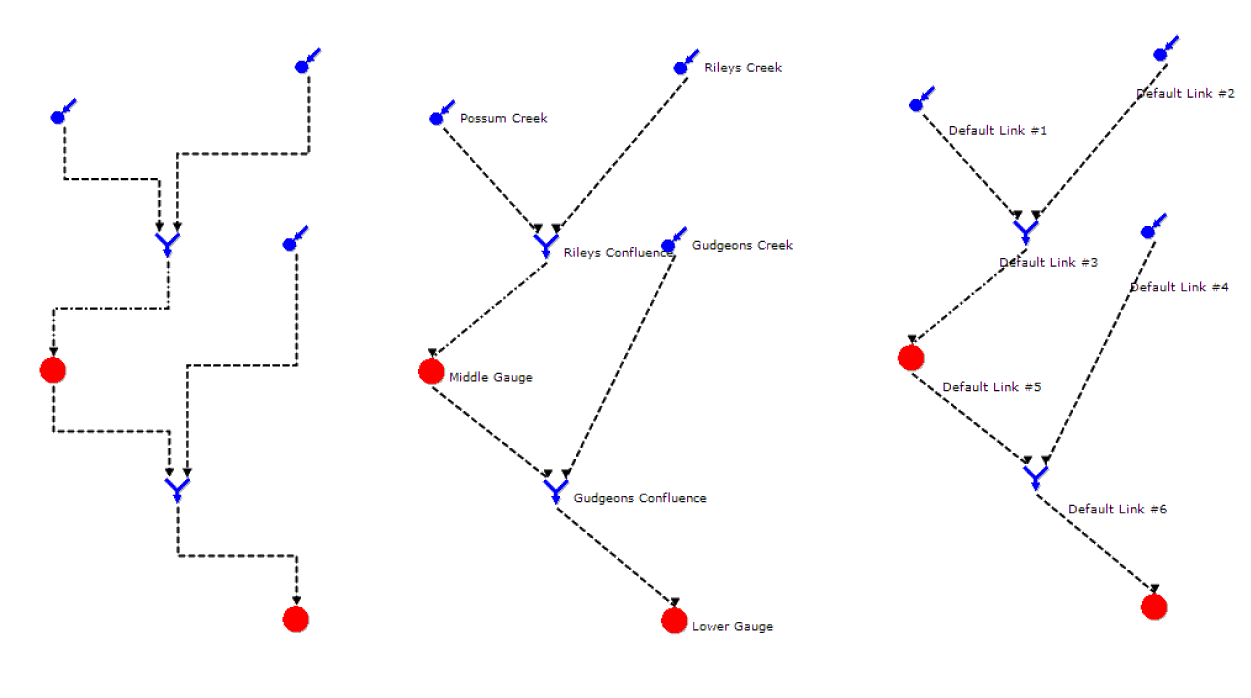
You can change the display of a model in the Schematic Editor in several ways using the Schematic Editor options toolbar and Schematic Editor grid toolbar. The former deals primarily with components drawn in the Schematic Editor, whereas the latter involves display elements. The schematic in the centre of Figure 2 represents one without any options enabled, and the surrounding schematics show the effect when the controls on toolbar buttons are turned on. Figure 13 shows the contextual menu when you right click in the Schematic Editor.
Figure 1. Schematic Editor contextual menus
Schematic Editor options toolbar (refer to Figure 2)
- You can work with links and nodes in the Schematic Editor using Allow Link Dragged. This button allows you to disconnect the downstream end of a link from the node to which it is attached, and then reconnect that link to the upstream inlet of another node. You can use this feature to insert new nodes into a schematic without losing the configuration of existing links.
- Straight Lines controls the representation of links. Source defaults to drawing links using orthogonal (elbow) lines. Click this button to change the default representation to straight lines. The left and centre schematics of Figure 15 show the difference between how a model will be represented after you press the bottom. The representation of any link can be controlled independently using the contextual menu in the Schematic Editor. Right-click the link and choose one of the options in the Link Type sub-menu. Each line has one control point which you can adjust to route the line around obstacles. The control point for an orthogonal line can only be moved in the vertical dimension whereas the control point for a straight line has no restrictions on its movement.
- Node Labels controls whether the names of nodes are shown in the Schematic Editor. Source defaults to displaying node names. The schematic on the centre of Figure 15 shows the behaviour of theSchematic Editor with the Node Labels control turned on.
- Link Labels controls whether the names of links are shown in the Schematic Editor. Source defaults to displaying link names. The schematic on the right of Figure 15 shows the behaviour of theSchematic Editor with the Link Labels control turned on.
- Track (Schematic Editor options toolbar) controls whether the Schematic Editor always scrolls to show components as they are selected in the Project Hierarchy. The default state of this button is off. In this mode, Source leaves the Schematic Editor window unchanged, regardless of any selections you may make in the Project Hierarchy. If you turn Track on, the Schematic Editor window will scroll to bring into view any node or link that you select in the Project Hierarchy. You can use this feature to locate components in large models.
- Overview Panel controls whether the Overview Panel is shown in the Schematic Editor. The default state of this control is off. The schematic on the bottom left of Figure 15 shows the behaviour of theSchematic Editor with the Overview Panel control turned on. You can use this button to obtain a thumbnail view of your entire schematic. You can drag the Overview Panel to any point within theSchematic Editor but you cannot pan the Schematic Editor by dragging within the Overview Panel.
- Pan - controls movement of the drawing surface. When this button is enabled, clicking and holding on any part of the drawing surface in the Schematic Editor moves the entire drawing surface. This is an alternative to using the scroll bars;
- Tool tips - controls the view of tool tips containing information about a node’s order in the flow sequence, its elevation and the node type. A storage node contains additional information including its height, capacity and surface area:
Tool tips on – when selected, clicking on any node in the Schematic Editor causes a small floating window to appear which contains additional information about that node;
Tool tips off – when selected, the floating windows do not appear; and
Tool tips locked – when selected, clicking any node in the Schematic Editor causes a small floating window to appear next to every node.
- Show/hide water user and bulk licensing links - controls the view of links between the following types of nodes:
- Supply point and water user nodes; and
- Bulk licensing and gauge nodes.
Figure 2. Schematic Editor options toolbar
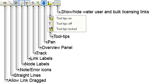
Figure 3. Schematic Editor options comparison
Schematic Editor grid toolbar (refer to Figure 4)
- Toggle display of the grid using Snap to Grid. The default state is off but the setting is saved with your project. Figure 5 compares the appearance of the Schematic Editor with the Snap to Grid control turned off (left) versus on (50px centre and 100px right). Turning this setting on does not affect the alignment of existing nodes. Alignment with the grid is only enforced when you drag a node. The default state is off but the setting is saved with your project. The grid does not need to be visible for alignment to occur;
- Change the frequency of grid lines using Set Grid Size. The default is 10 pixels but the setting is saved with your project. Figure 5 shows the appearance of the Schematic Editor with a grid setting of 10 pixels (centre) and 50 pixels (right). This is synonymous to right clicking on the Schematic Editor and choosing Grid Settings...;
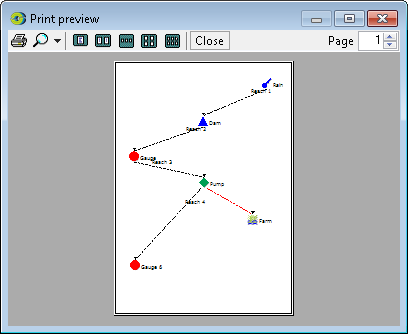
- You can view a sample printed copy of the model displayed in the Schematic Editor using Print (Schematic Editor grid toolbar). At present, the entire schematic is scaled to fit within a single A4 page in portrait mode. An example is shown in Figure 6;
- You can save a Source model in .JPEG format using Save as Image (in the Schematic Editor grid toolbar).This command opens a standard file dialog box so that you can choose where to save the image. At present, the entire schematic is scaled to fit within a single A4 page in portrait mode.
- You can view the zoom and undertake various zoom actions using the zoom icons on the right side of the toolbar:
- Current zoom displays the value of the zoom that is currently used in the Schematic Editor. This value has a range of of 10% - 200%;
- Zoom in (or Ctrl + on your keyboard) allows you to zoom into a particular part of the model. Similarly, Zoom out (or Ctrl - on your keyboard) allows you to zoom out. Both actions are performed in increments of approximately 10%; and
- The last two icons ensure that the entire model fits into the Schematic Editor screen. As its name suggests, Fit to width ensures that entire model is visible horizontally in the window. Clicking Fit to window will display the entire model in the window.
Figure 4. Schematic Editor grid toolbar
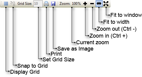
Figure 5. Snap to grid on/off comparison
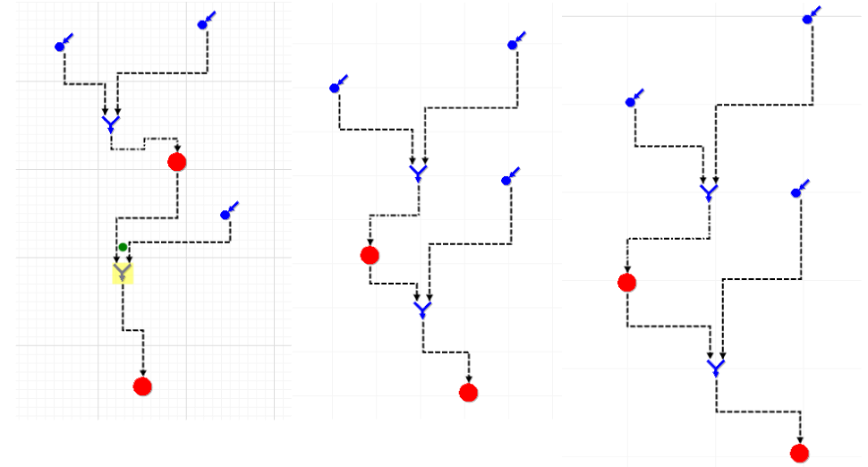
Figure 6. Schematic editor, Print Preview